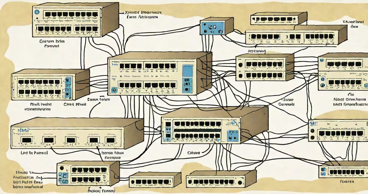
The cisco show spanning tree command displays real-time status of the Spanning Tree Protocol (STP) on a Cisco switch, revealing which ports are forwarding, blocking, or learning, and identifying the root bridge and path costs.
Spanning Tree Protocol prevents loops in redundant Layer 2 networks by placing certain ports into a blocking state. The show spanning-tree command reveals the current STP topology, including port roles (root, designated, alternate), port states (blocking, listening, learning, forwarding), and the elected root bridge. This information is essential for diagnosing connectivity issues, verifying STP convergence, and ensuring network stability.
For example, if a user reports intermittent access to a server connected to a specific switch port, running show spanning-tree may reveal that the port is stuck in the listening state-indicating a failure to converge. This insight allows network engineers to check for misconfigured STP settings, incorrect priority values, or physical layer problems.
When STP runs on a Cisco switch, it elects a single root bridge based on bridge ID (priority + MAC address). All other switches calculate the shortest path to the root and disable redundant paths to prevent loops. The show spanning-tree command displays the result of this election process and the current state of each port.
Each port is assigned a role: root (closest to the root bridge), designated (forwarding traffic toward the root), alternate (backup path), or backup (secondary link). A port in the blocking state does not forward frames but listens for BPDUs (Bridge Protocol Data Units) to detect changes in the network topology.
For instance, in a network with three switches connected in a ring, STP disables one port on the middle switch to break the loop. Running show spanning-tree on that switch shows the disabled port with a Role: Alternate and State: Blocking. This confirms STP is functioning as intended.
The command outputs several critical fields:
These values are updated dynamically during topology changes. For example, if a primary link fails, STP recalculates paths and promotes a previously blocked port to forwarding within 30 seconds under Rapid PVST+.
Many assume that a port in blocking state is "down" or disconnected. That's incorrect. A blocked port still receives BPDUs and participates in STP calculations-it's intentionally inactive to prevent loops, not malfunctioning.
Another misconception is that STP always blocks one link per redundant pair. While true in standard STP, Rapid PVST+ (per-VLAN STP) can allow multiple paths to be active simultaneously if different VLANs use different root bridges. This improves bandwidth utilization but requires careful planning.
A non-obvious detail: the show spanning-tree output includes a PortFast status. If a port is configured with PortFast and connects to a host, it skips the listening and learning stages and moves directly to forwarding. This reduces device boot time but can cause temporary loops if connected to another switch. Always verify PortFast is enabled only on end-user ports.
Consider a network with two switches, SW1 and SW2, connected via GigabitEthernet0/1 on both. SW1 has a lower priority (4096) than SW2 (32768), making SW1 the root bridge. On SW2, the command output shows:
Switch# show spanning-tree
VLAN0001
  Spanning tree enabled protocol ieee
  Root ID    Priority    32769
             Address     0011.2233.4455
             Cost        19
             Port        1 (GigabitEthernet0/1)
  ...
  Interface    Role   Sta   Cost      Prio.Nbr
  Gi0/1        Desg   FWD   19        128.1
  Gi0/2        Altn   BLK   19        128.2
Here, Gi0/1 is the designated port (forwarding), while Gi0/2 is the alternate port (blocked). The port cost of 19 reflects the default for Gigabit Ethernet. This confirms STP is operating correctly: only one path is active, preventing loops.
Different STP implementations affect output. The table below outlines key differences in behavior and output.
| STP Type | Root Bridge Election | Port States | Convergence Time | Per-VLAN Support |
|---|---|---|---|---|
| IEEE 802.1D (Standard STP) | Based on bridge ID | Blocking, Listening, Learning, Forwarding | 30-50 seconds | No |
| Rapid PVST+ | Same, but faster | Discarding, Learning, Forwarding | <1 second | Yes (per VLAN) |
| MSTP | Region-based | Same as Rapid PVST+ | <1 second | Yes (by region) |
Using show spanning-tree in a Rapid PVST+ environment shows separate entries for each VLAN. If VLAN 10 uses a different root bridge than VLAN 20, the output will reflect distinct root IDs and port roles per VLAN.
I once encountered a network where users lost access to a file server after a switch reboot. The show spanning-tree output revealed that the port connecting to the server was in discarding state. After checking the configuration, I found PortFast had been accidentally disabled on a port connected to a PC. Re-enabling PortFast restored connectivity immediately. This confirmed that PortFast affects STP behavior and must be verified on end-device ports.
Combine show spanning-tree with other diagnostic tools. Use show interfaces status to verify port operational status, and show ip interface brief to confirm IP addressing. For deeper analysis, use debug spanning-tree events to trace BPDU exchanges-but disable it quickly to avoid performance impact.
Always run show spanning-tree during troubleshooting sessions. It provides immediate visibility into loop prevention mechanisms and helps isolate failures caused by STP misconfiguration, hardware issues, or topology changes.