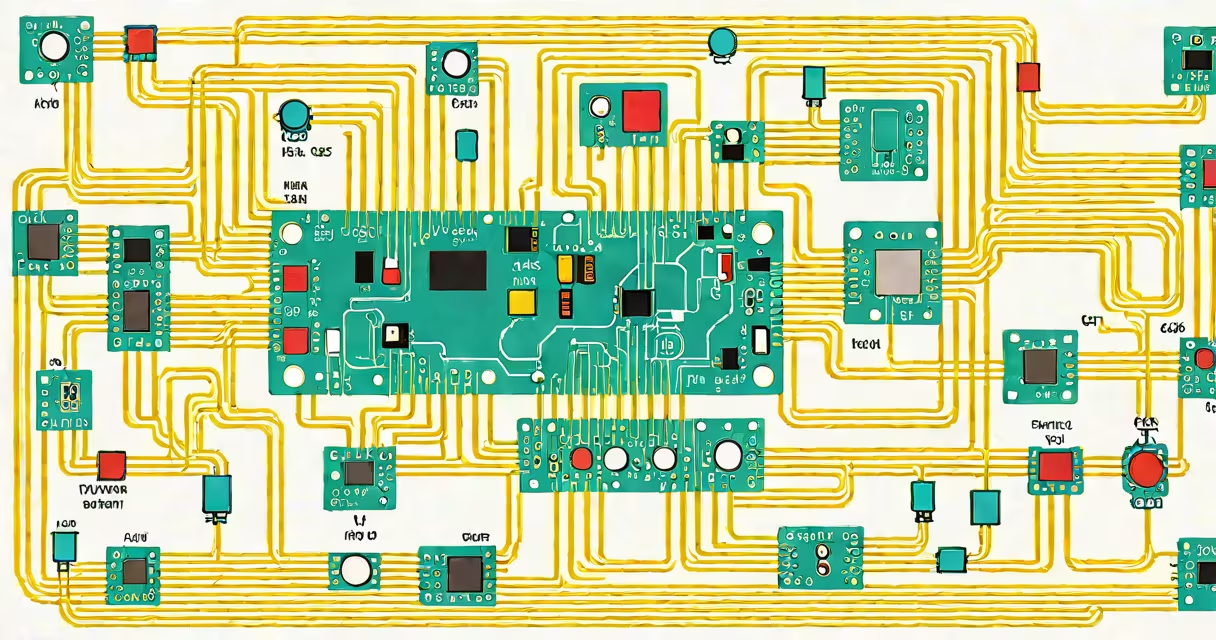
A schematic is a technical drawing that represents the components and connections in an electrical or electronic system using standardized symbols. It shows how parts link together functionally, not how they're arranged physically.
Schematics are used in electronics, engineering, and architecture to communicate design intent. They avoid confusion by using universal symbols-like a zigzag line for a resistor or a circle with a cross for a capacitor-so anyone familiar with the notation can interpret the layout regardless of language or region.
The term "schematic" comes from "schematism," meaning a structured plan. In practice, it's a blueprint for how signals flow through a device. For example, a car's ignition system schematic shows how the battery, switch, coil, and spark plugs connect-not how they're mounted under the hood.
Schematics use lines to represent wires and standardized shapes to depict components. These shapes follow international standards set by organizations like the International Electrotechnical Commission (IEC) and the American National Standards Institute (ANSI).
Each component has a unique symbol. A resistor appears as a rectangle or a series of steps; a transistor uses a triangle with a line and arrow pointing inward. The orientation matters: the base of a transistor symbol points toward the direction of current flow in analog circuits.
Connections are shown where lines meet. A dot at a junction indicates a direct electrical connection. If lines cross without a dot, they don't connect-this avoids ambiguity in complex designs.
Different fields use schematics for different purposes. The most common types are:
| Type | Use Case | Example |
|---|---|---|
| Electrical Schematic | Power systems, lighting, motors | House wiring diagram showing breakers, outlets, and switches |
| Electronic Schematic | Circuits with transistors, ICs, sensors | Arduino-based temperature controller with sensor, microcontroller, and display |
| Piping & Instrumentation Diagram (P&ID) | Industrial plants, HVAC systems | Chemical processing plant showing valves, pumps, and pressure gauges |
| Block Diagram | High-level system overview | Smartphone schematic showing CPU, memory, camera, and radio modules as blocks |
Block diagrams simplify complex systems by grouping functions into boxes. They're useful for planning and communication but lack detail for actual construction.
Many people think schematics show physical layout. They do not. A schematic for a printed circuit board (PCB) doesn't place components in their real positions-it only shows which pins connect to which.
Another mistake is assuming all lines represent wires. In reality, lines can represent signal paths, ground references, or even control logic. For example, a single line labeled "CLK" might carry a clock signal between a microprocessor and a memory chip.
Also, schematics aren't always drawn to scale. A 10kΩ resistor and a 100mH inductor may appear the same size on paper-even though their actual dimensions differ by orders of magnitude.
Consider a car stereo upgrade. The original factory system had a single speaker and no amplifier. You want to install a 4-channel amp and four speakers.
The schematic shows:
Using the schematic, you can verify that the amp receives power, grounds properly, and sends audio to the correct speaker. Without it, you risk shorting the system or damaging the head unit.
I once installed a custom audio setup in a 2015 Honda Civic. I relied on a schematic from a repair manual. When the subwoofer didn't work, I traced the signal path and found a missing ground connection. The schematic made the fault visible in seconds.
A schematic is not a wiring diagram in the traditional sense. While both show connections, a wiring diagram often includes physical routing, wire gauge, and terminal locations. A schematic focuses solely on logical relationships.
It's also not a PCB layout. The PCB layout shows where components are placed on the board and how traces are routed. Two boards can have identical schematics but different layouts due to space constraints or heat dissipation needs.
Finally, a schematic isn't a simulation. Tools like SPICE simulate behavior based on the schematic-but the schematic itself is static. It defines structure, not performance.
Without schematics, building or repairing electronic devices would require reverse-engineering every connection. They enable collaboration across teams and countries. A technician in Germany can fix a device designed in Japan using the same symbols and conventions.
According to IEEE Standard 315-1975, "The purpose of a schematic is to convey functional relationships among components." This standard remains foundational in electrical engineering education and certification.
When troubleshooting, engineers start with the schematic. It's faster than probing every pin. You can trace voltage drops, identify open circuits, or spot incorrect polarity-before touching a multimeter.
For hobbyists, schematics are essential for building projects safely. A 5V LED circuit with a 220Ω resistor won't work if the resistor is reversed. The schematic makes the correct orientation clear.
Understanding what schematic means allows you to read, build, and debug electronic systems. It's not about artistry-it's about clarity. A well-made schematic reduces errors, speeds up development, and prevents damage.
Diagnosing a malfunction, the schematic is your map. Always refer to it first.